Floor tile patterns in 3ds Max for herringbone and L-shaped rooms
Build floor and wall tile patterns in 3ds Max, from herringbone to concave rooms. Learn where Boolean cuts fail and how to map UVs.
Flooring in architectural visualisations often gives the render away when built purely with flat textures. At glancing camera angles, bump and normal maps look paper-thin, while displacement maps demand heavy memory and round off tile edges unnaturally.
To get convincing specular highlights along bevels and genuine contact shadows inside grout lines, floor patterns need physical geometry — and the real struggle begins the moment a room is not a simple rectangle.
This guide outlines the critical dimensions of standard architectural patterns, walks through manual modelling in native 3ds Max, and demonstrates how to handle complex concave perimeters without topology errors.
Before modelling: pattern geometry and proportions
Every geometric flooring pattern depends on an exact ratio between plank width, length, and grout joint spacing so the layout interlocks cleanly without creeping gaps.
Starting values used in this guide:
| Pattern | Plank dimensions | Joint type | Grout width | Edge bevel |
|---|---|---|---|---|
| Straight wood strip | 10 × 40 cm | Parallel courses | 1.5 mm | 1.0 mm |
| Herringbone | 12 × 60 cm | 90° interlocking flank | 2.0 mm | 1.5 mm |
| Chevron (French point) | 12 × 50 cm | 45° or 60° mitered tip | 2.0 mm | 1.5 mm |
| Rectified porcelain | 60 × 60 cm | Continuous grid | 1.5 mm | 0.8 mm |
| Hexagonal tile | 15 cm side | Alternating vertices | 3.0 mm | 1.5 mm |
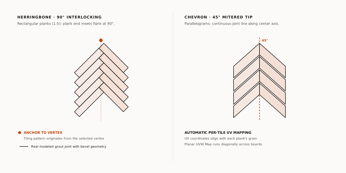
In patterns such as herringbone, the ratio of plank width to length must be an exact integer (1:4, 1:5, or 1:6). If a board measures 12 cm wide by 58 cm long, its 90-degree intersection leaves a creeping error that compounds visibly across the room.
Manual modelling with Editable Poly and Booleans
To build a herringbone floor across a rectangular room in native 3ds Max:
- In the Top viewport, create a Box matching one plank’s dimensions (e.g. Length 60 cm, Width 12 cm, Height 1.5 cm).
- Right-click the object and pick Convert To > Editable Poly.
- At Edge level, select the top perimeter edges and apply Chamfer with an amount of 1.5 mm and 2 segments to model the beveled rim.
- Rotate the plank 45 degrees along the Z axis. Clone another instance turned 90 degrees against the side of the first to create the initial L-module.
- Use Tools > Array (or hold Shift while dragging) to replicate rows across the entire floor surface until the room footprint is covered.
- Select one plank, open the Modify panel, and use Attach List to merge all cloned planks into a single composite mesh.
- Create a cutting volume matching the room’s perimeter walls by drawing a closed Rectangle spline and applying an Extrude modifier.
- With the merged plank object selected, navigate to Create > Geometry > Compound Objects > ProBoolean, choose the Intersection operation, and click Start Picking on the cutting prism.
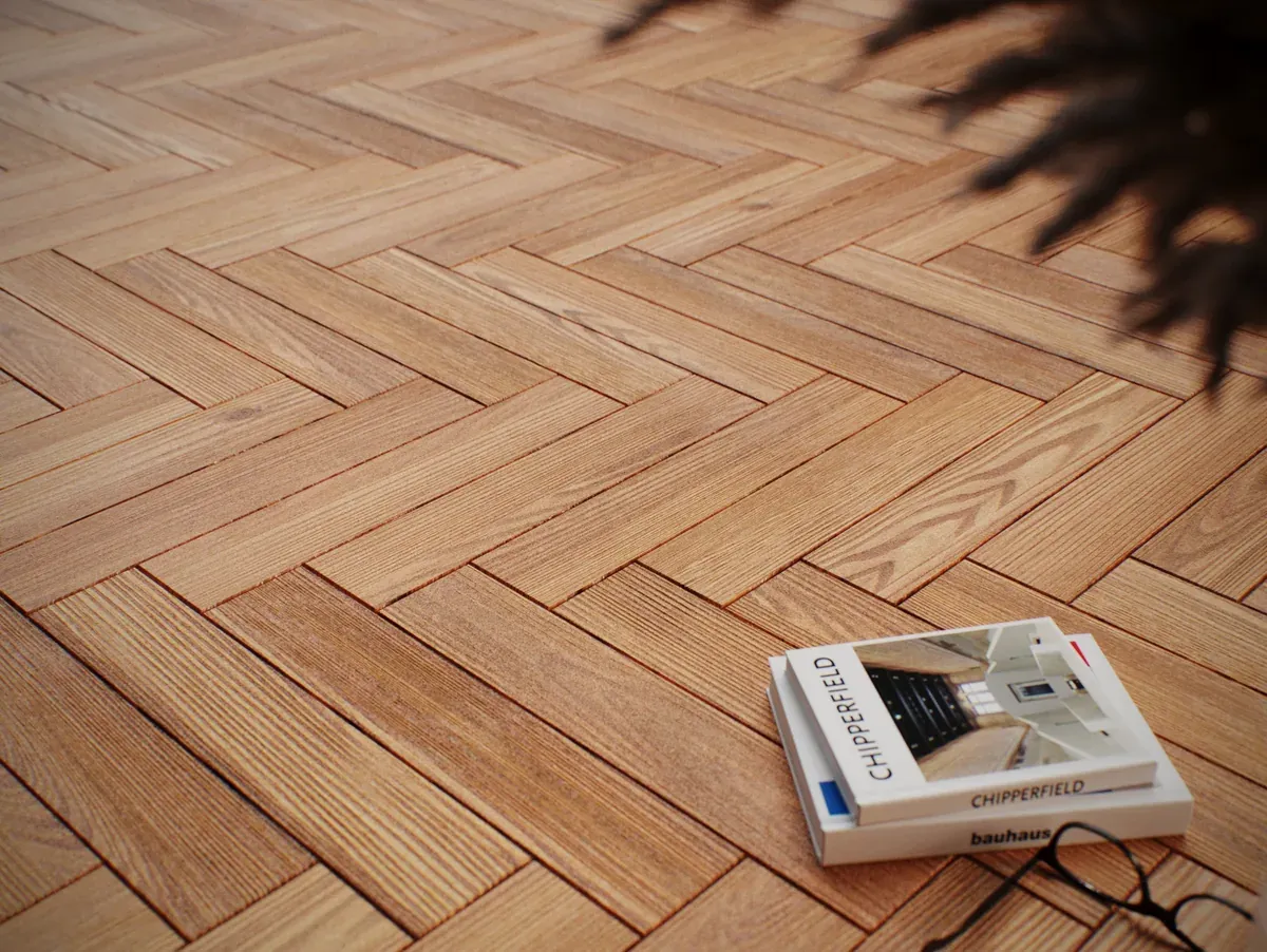
The Boolean cut clips excess boards outside the boundary, leaving the floor contained within the room walls.
Where the manual method breaks down
While this technique works for basic rectangular boxes, it collapses under realistic architectural conditions:
- Slow execution and failures on concave outlines. Boolean operations across hundreds of chamfered pieces are slow and can fail on concave outlines, such as L-shaped rooms, pool cutouts, or pillar notches.
- Misaligned UV mapping. A planar UVW Map applied over the whole set runs in one direction, so the grain does not follow each board at 45° and 90°.
- Costly revision cycles. If the designer shifts a door opening by 20 cm or repositions a kitchen island, the entire floor must be rebuilt: undoing the Boolean, resetting the array, attaching the objects, and trimming again.
In production projects with multiple rooms and frequent revisions, assembling flooring by hand drains hours into purely mechanical rework.
Parametric layout with Floor Tiler PRO
Floor Tiler PRO replaces manual cloning and risky Boolean cuts with a single parametric modifier, compatible with 3ds Max 2024 through 2027. Applied directly over any floor or wall face, it calculates true perimeter clipping at render time.
- Select your floor base surface (a plane, mesh, or Editable Poly).
- Apply the Floor Tiler PRO modifier in the stack.
- Choose your desired pattern from 11 built-in options (Herringbone, Chevron, Hexagon, Basket Weave, etc.) or pick a custom user-modeled tile.
- Adjust spinners for plank dimensions, bevel width, and grout thickness.
- Use Anchor to Vertex and click a boundary vertex to anchor where the tiling pattern originates.
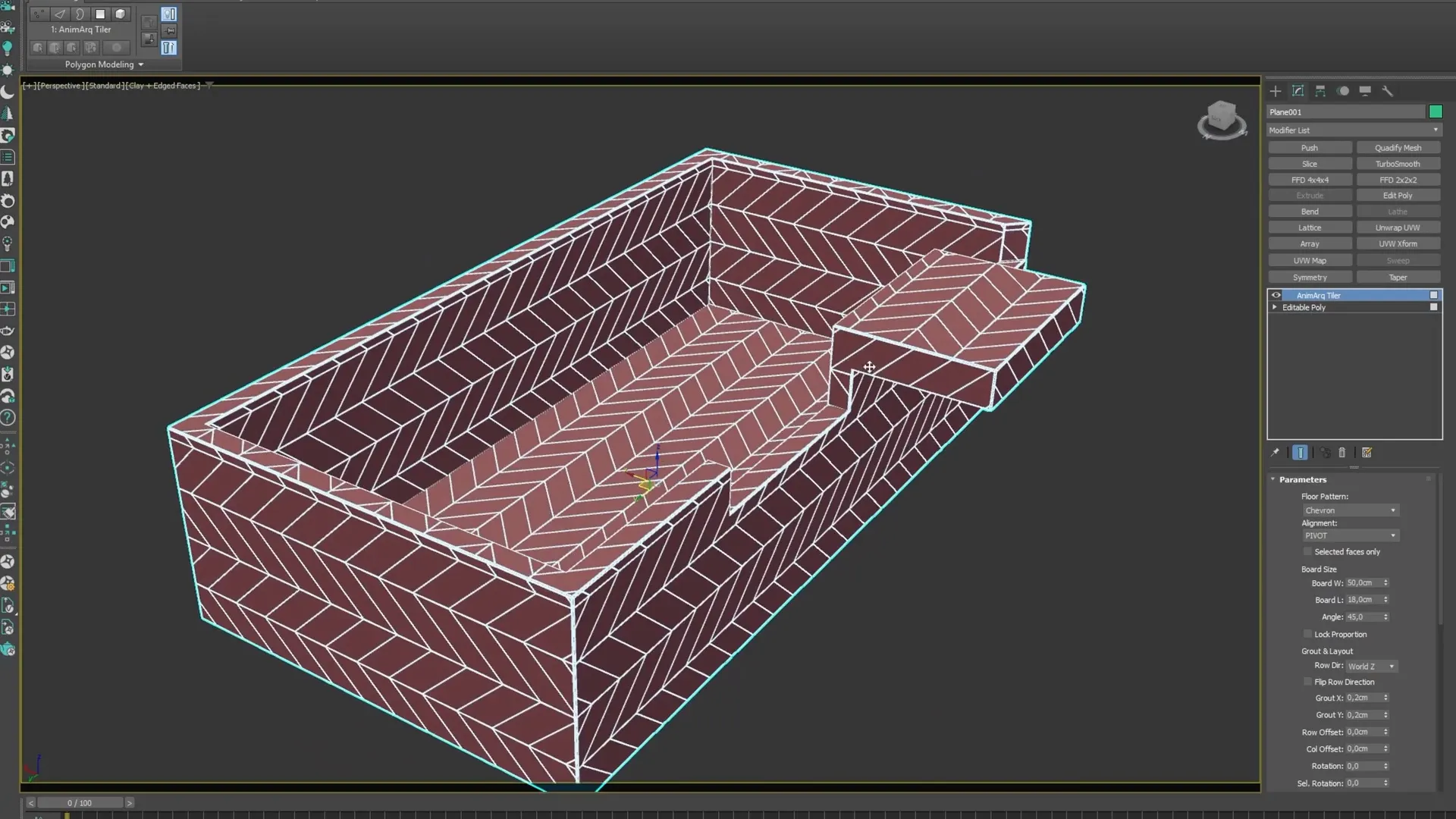
The underlying engine executes true concave clipping: L-shapes, pool cutouts, stair wells, and wall notches are cleanly trimmed with mathematical precision, leaving no stray slivers or rogue diagonal edges.
Texture mapping comes pre-configured with Real-World and Per-Tile UV modes. In Per-Tile mode, UV coordinates follow the direction of each individual plank, with manual rotation and random variation per tile, delivering realistic wood grain without requiring manual Unwrap UVW editing.