3ds Max Physical Camera settings for architectural renders
Set up the 3ds Max Physical Camera for architecture: choose focal lengths, calculate field of view and correct verticals.
Two persistent framing errors frequently undermine architectural renders: converging vertical lines that make buildings appear to tilt backwards, and wide-angle distortion that stretches living rooms into unnatural corridors.
In architectural photography, photographers solve these issues using tilt-shift lenses and consistent tripod heights. In 3ds Max, the native Physical Camera reproduces these optical principles using a 36 mm full-frame sensor, integrated perspective controls, and precise focal length parameters.
This guide provides tested focal length ranges for interiors and exteriors, the trigonometric formula for horizontal field of view (FOV), and step-by-step instructions to keep vertical lines plumb.
Focal lengths and horizontal field of view (FOV)
By default, the 3ds Max Physical Camera uses a sensor width of 36 mm (standard 35 mm full-frame format). The horizontal angle of view depends directly on the lens focal length:
FOV = 2 × atan(36 ÷ (2 × f))
In this formula, f represents the lens focal length in millimeters, and the arctangent result (atan) is converted from radians to degrees.
Worked calculation for a 24 mm focal length:
36 ÷ (2 × 24) = 36 ÷ 48 = 0.75atan(0.75) ≈ 0.6435 radians- Convert to degrees:
0.6435 × (180 ÷ π) ≈ 36.87° FOV = 2 × 36.87° ≈ 73.7°
Field of view values for typical architectural focal lengths on a 36 mm sensor:
| Focal length (f) | Field of view (FOV) | Recommended application |
|---|---|---|
| 18 mm | 90.0° | Tight powder rooms (extreme limit) |
| 20 mm | 84.0° | Compact bathrooms and utility spaces |
| 24 mm | 73.7° | Interior standard: open living areas and bedrooms |
| 28 mm | 65.5° | Large interior spaces with negligible perimeter distortion |
| 35 mm | 54.4° | Transition: spacious interiors or close-range facades |
| 50 mm | 39.6° | Exterior facades matching human eye proportions |
| 70 mm | 28.8° | Free-standing buildings and elevation details |
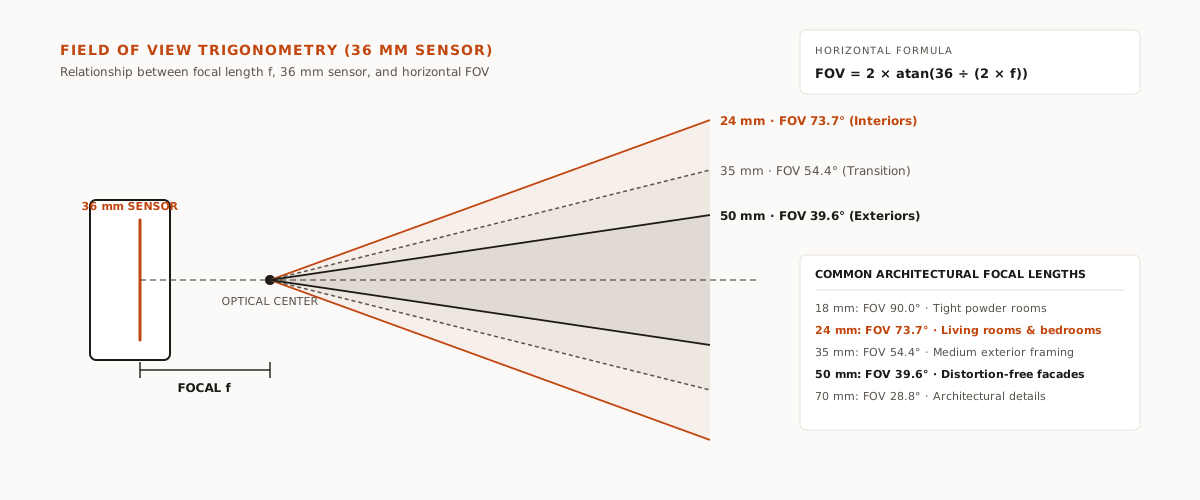
For residential interiors, the 24 mm to 28 mm range balances context with geometric fidelity. Dropping below 20 mm noticeably stretches furniture and perimeter objects. For exterior elevations, using 50 mm to 70 mm preserves accurate building proportions and setbacks.
Camera heights across scene types
The Z-axis elevation establishes the visual balance between floors and ceilings:
- Pedestrian eye level (exterior facades): 1.50 m to 1.60 m. Replicates the standing sightline of an adult on the sidewalk.
- Residential interiors (living areas): 1.20 m to 1.40 m. Prevents dining tables from obstructing chairs and maintains head clearance.
- Kitchens and counters: 1.35 m to 1.45 m. Provides a clear view over countertop surfaces without pitching downward.
Step-by-step setup in 3ds Max
Setting up an architectural camera follows five steps using native tools:
1. Create the Physical Camera
- In the Command Panel, go to Create > Cameras > Standard.
- Click the Physical button.
- In the Top viewport, click at the observer position and drag toward the subject to position the camera body and its Target.
2. Level camera and target heights
- Select both the camera body and its Target.
- In the Z-coordinate field on the bottom status bar, enter the target elevation (for example,
1.30 m). - Keeping camera and target at identical Z-heights aligns the optical axis parallel to the ground, creating a clean two-point perspective.
3. Adjust focal length
- Select the camera body and open the Modify panel.
- In the Physical Camera rollout, under the Film/Sensor group, confirm that the Width field is set to 36.0 mm.
- In the same rollout, under the Lens group, select Focal Length and enter the desired value (such as
24.0 mmfor interiors or50.0 mmfor facades).
4. Enable perspective correction
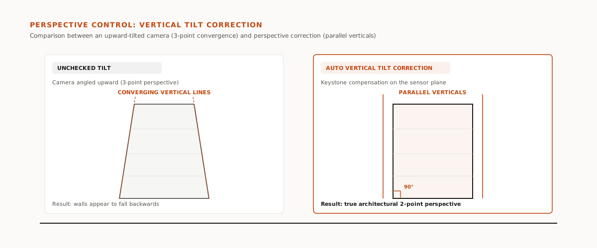
When framing taller buildings, pitching the camera upward causes vertical edges to converge.
To restore parallel vertical edges:
- In the Modify panel, scroll down to the Perspective Control rollout.
- Check Auto Vertical Tilt Correction. 3ds Max shifts the film plane offset to restore vertical alignment across all architectural walls.
- For manual control without pitching the camera body, keep camera and target level and adjust the Vertical spinner under Lens Shift.
5. Enable Safe Frames
- Press C in the active viewport to switch to the camera view.
- Press Shift + F to toggle Show Safe Frames. Perimeter masks display the exact crop rectangle matching your render setup.
Where standard setups break down
Three frequent mistakes cause framing issues:
- Using ultra-wide lenses in small spaces: In a 2 m × 1.5 m bathroom, using 16 mm distorts sanitary fixtures. Keep the lens at 24 mm, place the camera body outside the room, and configure the Miscellaneous rollout (Clipping & Environmental Ranges: turn clipping on, set Near to slice through the obstructing wall without rendering it).
- Forcing tilt correction on aerial views: On high 45° bird’s-eye views, enabling Auto Vertical Tilt Correction stretches building foundations unnaturally. For high-angle shots, three-point perspective is natural and should remain uncorrected.
- Uncontrolled Target movement: Moving the target freely in perspective views knocks it out of level. Use Truck Camera in the camera viewport navigation controls for fine horizontal reframing.
Calculating focal lengths for a 36 mm sensor and enabling perspective correction produces clean architectural compositions adhering to professional visualization standards.