Draw precise lines in 3ds Max with keyboard entry
Draw precise lines in 3ds Max with exact distance and angle. Compare Keyboard Entry and Grid Snap, then create editable splines.
Drawing accurate room perimeters, ceiling drops, baseboards, and millwork profiles in 3ds Max often tests an artist’s patience. The software was originally built around visual, freehand modeling, where the native line tool assumes you want to click and drag loosely across the viewport.
When an architectural drawing demands exact figures — such as a 4.20 m wall run at 90 degrees followed by a 1.80 m chamfer at 45 degrees —, guessing with the mouse is unacceptable. Many 3D artists resort to opening AutoCAD solely to draft a 2D boundary and re-import it back into 3ds Max via DWG.
This guide compares native 3ds Max techniques for dimensioned drafting, highlights the friction points in standard tools, and introduces direct polar keyboard entry.
Drafting workflows in 3ds Max: a technical comparison
3ds Max offers several native ways to pursue millimeter precision in splines, each carrying distinct levels of workflow friction:
| Method | Direct polar input (distance + angle) | Angular snapping | Drawing speed | Output geometry |
|---|---|---|---|---|
| Native freehand Line | No (approximate mouse dragging) | Shift locks to 90° | Fast, but inaccurate | Standard spline |
| Grid Snap + Transform Type-In (F12) | Indirect (vertex-by-vertex adjustments) | Fixed to grid intervals | Slow (halts the drawing flow) | Editable Spline |
| Native Keyboard Entry rollout | No (absolute X, Y, Z coordinates only) | None | Requires manual trigonometry | Editable Spline |
| Dynamic Line | Yes (typed on keyboard, confirmed with Enter) | Ortho 90° and Polar 45°/15° | Continuous AutoCAD flow | Editable Spline |
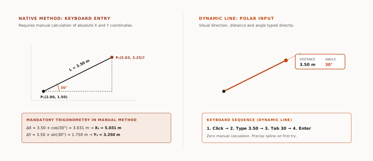
Without a dynamic input system, laying out angled walls in native 3ds Max forces you to solve Cartesian coordinates before placing each vertex.
Manual drafting with Grid and Transform Type-In
To draw a line to exact dimensions using native 3ds Max tools exclusively:
- Right-click the Snaps Toggle icon on the main toolbar to open the Grid and Snap Settings dialog.
- Under the Home Grid tab, set Grid Spacing to a unit suited to your project layout (e.g. 0.10 m or 1.0 m).
- Under the Snaps tab, clear freeform options and check only Grid Points. Close the dialog and press S to engage snapping.
- Go to the Create > Shapes > Splines panel and click Line.
- Click in the viewport to place your start vertex on a grid point. Hold Shift as you move the mouse to restrict movement to 90° orthogonal directions (0°, 90°, 180°, or 270°).
- For dimensions that do not align with grid increments or run at arbitrary angles (such as 3.42 m at 30°), click an estimated position to create the vertex.
- Switch to the Modify panel, enter the Vertex sub-object level (press 1), select the newly placed vertex, and press F12 to open the Transform Type-In dialog.
- Enter the required relative offsets under Offset: World for X and Y to move the vertex into its exact mathematical position.
Another native alternative is the Keyboard Entry rollout in the Line tool, which provides X, Y, and Z fields alongside Add Point, Close, and Finish buttons. However, it requires entering cumulative absolute Cartesian coordinates for each vertex sequentially and clicking Add Point (using Close to seal the loop or Finish to end an open spline), requiring mental arithmetic for every wall turn.
Where the manual method breaks down
The native 3ds Max workflow handles simple boxes adequately, but fails when confronted with realistic architectural layouts:
- Lack of native polar input. There is no default prompt in 3ds Max where you can aim a direction and type “3.50” followed by “45°”. The software forces you to calculate trigonometric sines and cosines (ΔX and ΔY) or adjust points after the fact.
- Constant workflow interruptions. Exiting creation mode, entering vertex sub-object levels, opening Transform Type-In (F12), and typing coordinates destroys drafting rhythm. A simple ten-vertex perimeter turns into a multi-minute chore.
- Shift only handles 90 degrees. Native angle locking in 3ds Max only snaps to orthogonal axes. There is no built-in mechanism to cycle polar angle guides at 45° or 15° while drawing a spline.
- Decimal separator conflicts. On Windows machines using European or South
American locale settings, typing a period in certain 3ds Max spinners (
1.5) silently truncates the value to1, requiring commas or system locale changes.
Guessing vertex positions and fixing them coordinate by coordinate in the modifier stack is the slowest path to building architectural splines.
AutoCAD-style drafting with Dynamic Line
Dynamic Line is a free native plugin for 3ds Max (versions 2022 through 2027) that brings the familiar AutoCAD command line and polar drafting workflow directly into the 3ds Max viewport.
- Start Dynamic Line.
- Click once in the viewport to establish your start point.
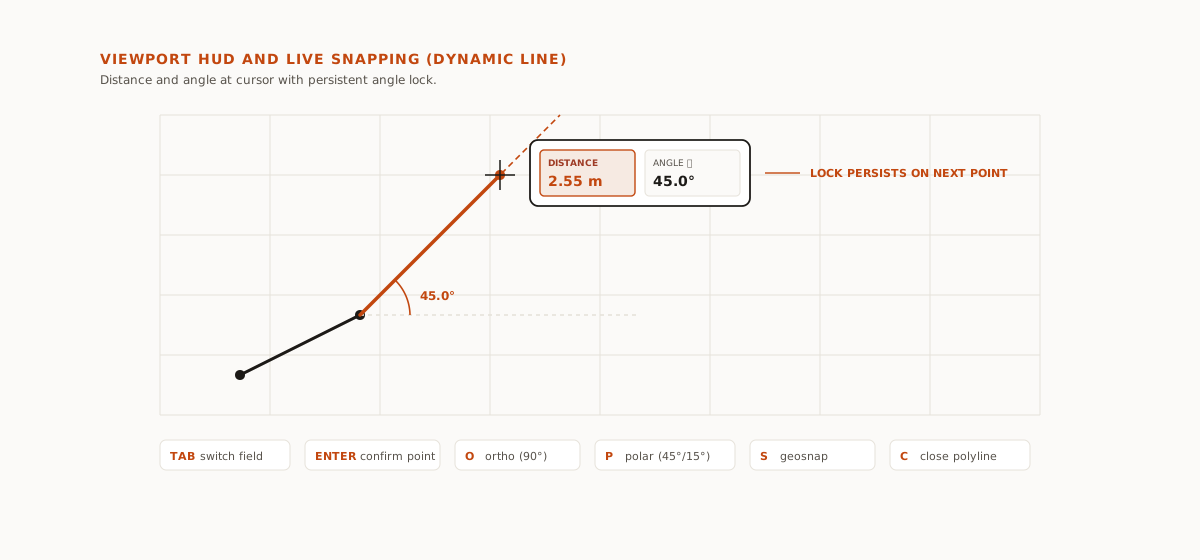
- Aim the cursor in your intended direction: a floating HUD attached to the mouse displays distance and angle in real time.
- Type the exact distance (e.g.
3.50or3,5— the custom parser handles either decimal separator). - Press Tab to switch to the angle field and enter your angle (e.g.
45). - Press Enter to confirm the segment.
- To close the polyline once you have 3 or more vertices, press the C key; to end an open line, press Esc or right-click.
The tool includes single-key snapping toggles: pressing O enables Ortho mode (locked to 90° intervals), pressing P cycles Polar snapping (45°, 15°, or off), and pressing S activates GeoSnap to lock onto vertices and endpoints of existing scene geometry.
When you lock an angle using Tab, that direction persists across subsequent segments — letting you rapidly type successive lengths without having to re-aim the angle every time.
The final output is a native Editable Spline, completely compatible with modifiers such as Extrude, Sweep, Bevel Profile, and Lathe.